BLDC motors with field-oriented control
The integration of power electronics in a brushless DC motor not only allows the
motor to be controlled in a very simple and elegant way, but also offers a wide range of implementable control algorithms.
State-of-the-art is the field-oriented control (FOC), based on the mathematical description of the motor and the transformation of alternating variables into direct variables. In this context, FOC offers advantages for the power electronics, improves the dynamic behavior and delivers an optimal torque. A smooth torque is one of the most important quality parameters for the operation of electric drives, because torque harmonics can lead to mechanical vibrations in the complete drive system. Torque fluctuations are often detrimental to the connected loads. Gearboxes between the motors and the load machines are particularly vulnerable due to these fluctuations. In addition, torque harmonics can contribute to increased noise.
From a control engineering perspective, FOC is comparable to the control of a brushed DC motor. By decoupling the magnetic flux and the torque, the typical behavior of a brushed DC motor (GR motor) is achieved. The basic concept of FOC is the consideration of temporal instantaneous values. Thus, the alternating electrical quantities of a three-phase motor are not treated as fixed in space, but rotate with the rotor. This means that the three phase currents measured at the stator are converted into rotor coordinates. Since the reference frame is static, the controller can work with DC quantities instead of AC quantities.
Basically, there are two general methods of FOC. Both methods differ in the way the rotor angle or position detection is determined. In direct FOC, the angle is calculated by terminal voltage and the terminal currents, while in indirect FOC the rotor position is measured. Thus, an additional position detection is needed for indirect FOC. A prerequisite for both methods and good control quality is that the motor parameters of the controller match the actual parameters of the motor.
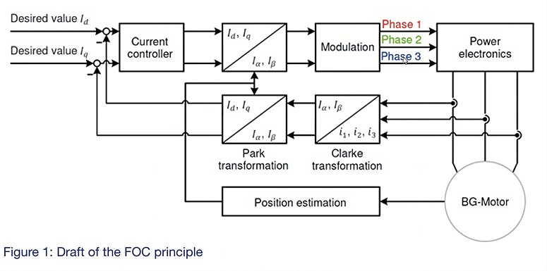
The DC quantities are divided into a field-forming (d) and a torque-forming (q) component. Since the magnetic flux in the air gap is built up exclusively by the permanent excitation, the stator currents have almost no flux-forming component. Due to the surface magnets of the rotor, the set point for the field-forming current (I_d) is set to zero. The output of the current controller represents the reference voltages in the rotor coordinates. To control the three-phase stator current, the FOC algorithm generates a three-phase voltage vector. This is based on the conversion of the rotor-fixed d/q quantities into stator-fixed α/ quantities. Converting the physical current into a rotation vector using the Clarke and Park transformations makes the torque and magnetic flux time-independent quantities. An extended proportional-intergral (PI) controller with proportional gain and integral time parameters is used as the control algorithm. These parameters depend on the motor inductance, winding resistance, and the complete signal processing chain.
DC motors are designed so that the magnetic flux in the stator and rotor are each 90° from each other, which allows the motor to produce maximum torque. FOC technology transforms the motor currents into two-axis vectors comparable to those in a DC motor.
The process begins with a measurement of the motor‘s three phase currents (i_1, i_2 and i_3). Because the sum of the three current values is zero at any point in time, in practice only two of the three currents are measured and the value of the third current can be calculated from the measured values obtained. This results in an immediate reduction in hardware costs, since only two current sensors are required. With the information of the stator currents and the rotor angle, the values are transformed into a coordinate system to calculate the polar coordinates consisting of magnitude and angle. This means that measured motor currents are mathematically transformed from a threephase static reference system of the stator winding to a rotating reference system. The rotating system consisting of the d and q components can be processed very easily by a PI controller. Similarly, the voltages to be applied to the motor are mathematically transformed from the d/q system of the rotor to a three-phase reference system. When a sinusoidal input current is applied to the stator, this produces a rotating magnetic flux. The speed of the rotor is directly related to the rotating magnetic flux.
Thanks to modern microprocessors, precise current sensing and fast power electronics, the torque and speed of the motor can be controlled very well. Using pulse width modulation (PWM), the magnitude and angle values are converted into three-phase currents by controlling the inverter‘s high-side and low-side switches accordingly. Thus, the DC voltage is switched to the respective motor phases by switching the power transistors and a specific current is impressed by PWM. The aim of the modulation is the readjustment of a sinusoidal voltage. MOSFETs are used as power semiconductors for the three half-bridges. Furthermore, the power electronics consist of an intermediate circuit capacitor and additional filter technology. The control electronics not only regulate and control the electric motor, but also perform communication tasks and monitoring functions. The current must be measured cyclically so that a new actual value is available for each PWM cycle and can be processed by the control system. It is particularly important that the measured current is recorded and processed quickly so that it does not change noticeably during the runtime of the program.
In the FOC method, the three-phase winding of the motor is fed sinusoidally by PWM signals of the modulation. Due to the in principle finite switch-on and switch-off times of the power semiconductors, their drive signals are artificially delayed in order not to cause a bridge short-circuit when switching between positive and negative DC link voltage.
State-of-the-art is the field-oriented control (FOC), based on the mathematical description of the motor and the transformation of alternating variables into direct variables. In this context, FOC offers advantages for the power electronics, improves the dynamic behavior and delivers an optimal torque. A smooth torque is one of the most important quality parameters for the operation of electric drives, because torque harmonics can lead to mechanical vibrations in the complete drive system. Torque fluctuations are often detrimental to the connected loads. Gearboxes between the motors and the load machines are particularly vulnerable due to these fluctuations. In addition, torque harmonics can contribute to increased noise.
From a control engineering perspective, FOC is comparable to the control of a brushed DC motor. By decoupling the magnetic flux and the torque, the typical behavior of a brushed DC motor (GR motor) is achieved. The basic concept of FOC is the consideration of temporal instantaneous values. Thus, the alternating electrical quantities of a three-phase motor are not treated as fixed in space, but rotate with the rotor. This means that the three phase currents measured at the stator are converted into rotor coordinates. Since the reference frame is static, the controller can work with DC quantities instead of AC quantities.
Basically, there are two general methods of FOC. Both methods differ in the way the rotor angle or position detection is determined. In direct FOC, the angle is calculated by terminal voltage and the terminal currents, while in indirect FOC the rotor position is measured. Thus, an additional position detection is needed for indirect FOC. A prerequisite for both methods and good control quality is that the motor parameters of the controller match the actual parameters of the motor.
The DC quantities are divided into a field-forming (d) and a torque-forming (q) component. Since the magnetic flux in the air gap is built up exclusively by the permanent excitation, the stator currents have almost no flux-forming component. Due to the surface magnets of the rotor, the set point for the field-forming current (I_d) is set to zero. The output of the current controller represents the reference voltages in the rotor coordinates. To control the three-phase stator current, the FOC algorithm generates a three-phase voltage vector. This is based on the conversion of the rotor-fixed d/q quantities into stator-fixed α/ quantities. Converting the physical current into a rotation vector using the Clarke and Park transformations makes the torque and magnetic flux time-independent quantities. An extended proportional-intergral (PI) controller with proportional gain and integral time parameters is used as the control algorithm. These parameters depend on the motor inductance, winding resistance, and the complete signal processing chain.
DC motors are designed so that the magnetic flux in the stator and rotor are each 90° from each other, which allows the motor to produce maximum torque. FOC technology transforms the motor currents into two-axis vectors comparable to those in a DC motor.
The process begins with a measurement of the motor‘s three phase currents (i_1, i_2 and i_3). Because the sum of the three current values is zero at any point in time, in practice only two of the three currents are measured and the value of the third current can be calculated from the measured values obtained. This results in an immediate reduction in hardware costs, since only two current sensors are required. With the information of the stator currents and the rotor angle, the values are transformed into a coordinate system to calculate the polar coordinates consisting of magnitude and angle. This means that measured motor currents are mathematically transformed from a threephase static reference system of the stator winding to a rotating reference system. The rotating system consisting of the d and q components can be processed very easily by a PI controller. Similarly, the voltages to be applied to the motor are mathematically transformed from the d/q system of the rotor to a three-phase reference system. When a sinusoidal input current is applied to the stator, this produces a rotating magnetic flux. The speed of the rotor is directly related to the rotating magnetic flux.
Thanks to modern microprocessors, precise current sensing and fast power electronics, the torque and speed of the motor can be controlled very well. Using pulse width modulation (PWM), the magnitude and angle values are converted into three-phase currents by controlling the inverter‘s high-side and low-side switches accordingly. Thus, the DC voltage is switched to the respective motor phases by switching the power transistors and a specific current is impressed by PWM. The aim of the modulation is the readjustment of a sinusoidal voltage. MOSFETs are used as power semiconductors for the three half-bridges. Furthermore, the power electronics consist of an intermediate circuit capacitor and additional filter technology. The control electronics not only regulate and control the electric motor, but also perform communication tasks and monitoring functions. The current must be measured cyclically so that a new actual value is available for each PWM cycle and can be processed by the control system. It is particularly important that the measured current is recorded and processed quickly so that it does not change noticeably during the runtime of the program.
In the FOC method, the three-phase winding of the motor is fed sinusoidally by PWM signals of the modulation. Due to the in principle finite switch-on and switch-off times of the power semiconductors, their drive signals are artificially delayed in order not to cause a bridge short-circuit when switching between positive and negative DC link voltage.
In principle, field-oriented control requires a relatively high computing time, since the rotating variables must first be converted in order to use them in the control loop, and then the manipulated
variables must be converted back. The disadvantage here is the high computational cost for the
microcontroller, whose performance limits the dynamic behavior of the control. With the FOC, however, it is possible to control the torque and the flux separately. In this way, brushless DC motors
have the same advantages as brushed DC motors. Compared to direct current control, field-oriented control allows higher voltage utilization and reduces current-proportional losses for the same
power. This method thus enables better efficiency than direct current control.
Fieldoriented Control (FOC)
Block Commutation
Comparison of regulation and control types using the example of a BLDC Dunkermotor BG 65Sx25 24V
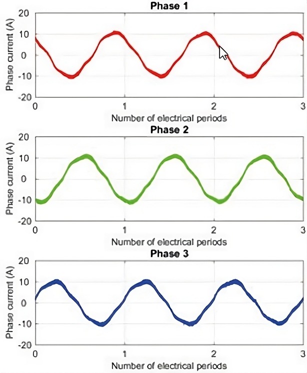
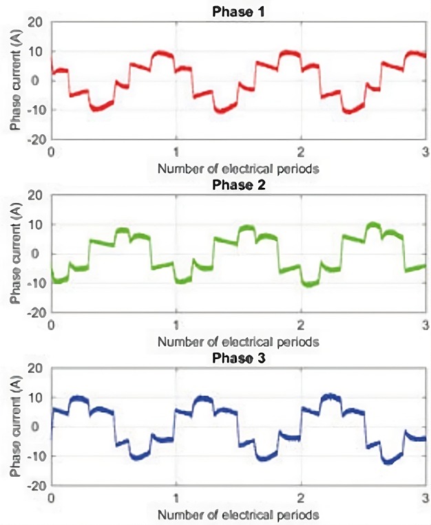
Compared to block or trapezoidal commutation, FOC produces maximum torque that is better aligned with the rotor field. Efficiency can be increased by the sinusoidal voltages and currents of the FOC. The transitions between the stator states are homogeneous, which eliminates the torque dips in block commutation and improves the dynamics of the overall system.
Compared to block or trapezoidal commutation, FOC produces maximum torque that is better aligned with the rotor field. Efficiency can be increased by the sinusoidal voltages and currents of the FOC. The transitions between the stator states are homogeneous, which eliminates the torque dips in block commutation and improves the dynamics of the overall system.